Complete Caravan Diesel Heating & Ventilation System Engineering: Air-Fuel Density Balancing, Duct Static Pressure, and High-Altitude Integration
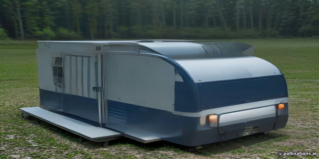
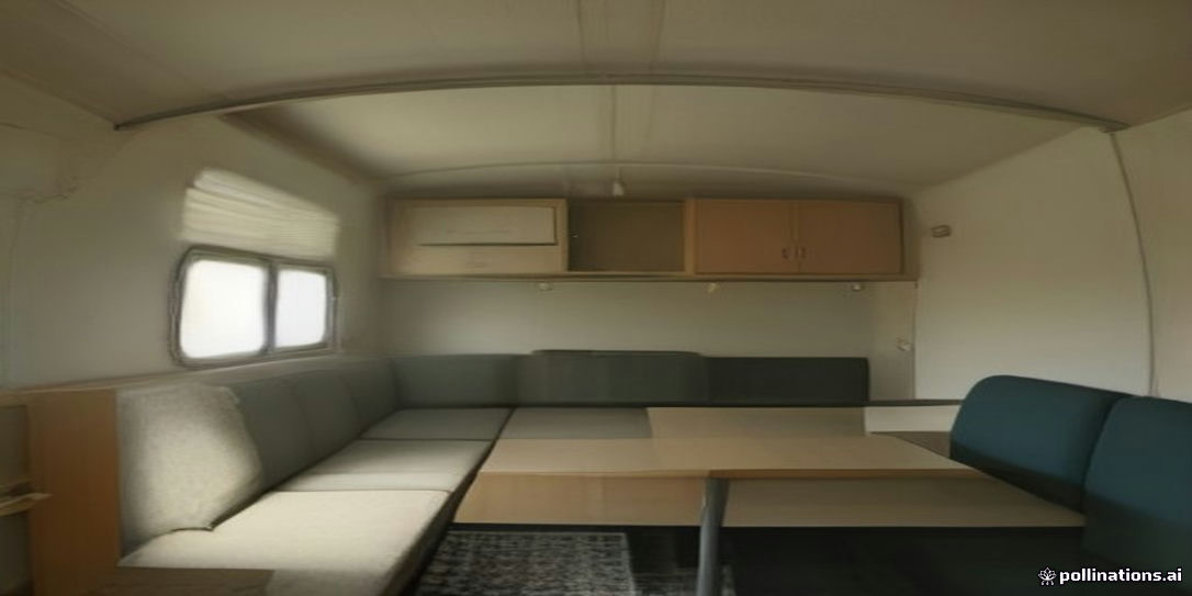
Designing a robust diesel heating and ventilation system for a caravan requires a comprehensive engineering approach that considers thermal dynamics, combustion efficiency, and environmental factors, especially at varying altitudes. This case study details the engineering design for a 5 kW diesel heater and ventilation system within a 28.5 m³ caravan cabin, specifically addressing the challenges posed by reduced air density at 2,500 meters above sea level. At this altitude, air density drops from 1.225 kg/m³ to 0.948 kg/m³, a significant 22.6% reduction that directly impacts combustion air supply and heat transfer efficiency.
Thermal and Volumetric Air Balance
Maintaining a healthy and comfortable cabin environment necessitates careful management of fresh air ventilation and heat loss. For a 28.5 m³ cabin, a minimum fresh air ventilation rate of 0.5 Air Changes Per Hour (ACH) is required to ensure adequate oxygen supply and mitigate CO2 buildup. This translates to a fresh air intake of 14.25 m³/hour (28.5 m³ * 0.5 ACH).
The 5 kW nominal heater capacity must account for heat losses through the caravan’s walls, windows, and ceiling, as well as the heat lost through the introduced fresh air. While precise heat loss calculations depend on insulation R-values and external temperatures, the 5 kW rating provides a substantial thermal input. The system must ensure efficient cabin air circulation to distribute this heat evenly, preventing cold spots and maximizing comfort. This often involves strategic placement of heat outlets and a return air path for the heater.
Example: Fresh Air Ventilation Calculation
- Inputs:
- Cabin Volume = 28.5 m³
- Minimum Fresh Air Ventilation = 0.5 ACH
- Formula: Required Fresh Air Volume (m³/hour) = Cabin Volume (m³) * Minimum Fresh Air Ventilation (ACH)
- Calculation: 28.5 m³ * 0.5 ACH = 14.25 m³/hour
- Result: The system must be designed to introduce at least 14.25 m³ of fresh air per hour into the cabin.
Combustion and Exhaust Circuit Engineering
The combustion process of a diesel heater requires a dedicated supply of fresh air and a safe, efficient exhaust path for combustion byproducts. Critical engineering considerations include:
- Combustion Air Intake: The combustion air must be drawn exclusively from outside the cabin to prevent the consumption of cabin air and to avoid drawing in any potentially harmful exhaust gases. This intake must be isolated from the cabin interior through airtight seals and dedicated ducting. A pre-filter on the intake can prevent dust and debris from entering the heater.
- Exhaust Pipe Design: The exhaust pipe must be constructed from high-temperature resistant materials, typically stainless steel. A crucial design element is the exhaust pipe slope. The pipe should have a continuous downward slope away from the heater to prevent condensation from accumulating and flowing back into the combustion chamber.
- Condensation Trap (Drain Loop): To further manage condensation, a drain loop or condensation trap should be incorporated into the exhaust system. This U-shaped section allows condensed water to collect and drain away, preventing it from reaching the heater or freezing within the exhaust line.
- Body Penetration Isolation: Where the exhaust pipe passes through the caravan body, robust insulation and sealing are paramount. High-temperature resistant grommets or seals must be used to prevent heat transfer to surrounding materials and to ensure an airtight seal, preventing exhaust gases from entering the cabin.
| Component | Function |
|---|---|
| Combustion Air Inlet | Supplies fresh, external air to the heater’s combustion chamber. Must be isolated from cabin air. |
| Exhaust Pipe | Routes hot combustion gases safely outside the caravan. Requires continuous downward slope to prevent condensation pooling. |
| Condensation Trap | Collects and drains condensed water from the exhaust gases, preventing it from returning to the heater or freezing in the exhaust line. |
| Body Penetration | Insulated and sealed passage where the exhaust pipe exits the caravan structure. Prevents heat transfer and exhaust gas ingress. |
| Muffler | Reduces noise generated by the exhaust gases. |
| Fuel Pump | Delivers diesel fuel from the tank to the heater. Its frequency is critical for air-fuel ratio, especially at altitude. |
| ECU | Electronic Control Unit; manages heater operations, including fuel pump frequency, fan speed, and safety functions. |
| CO Sensor | Critical safety device to detect carbon monoxide leaks within the cabin. Must be strategically placed. |
Heat Distribution Duct Engineering
Efficient heat distribution within the caravan relies heavily on a well-designed ducting system. For this 5 kW heater, 75mm diameter ducts are specified, with a maximum length of 4.5 meters and a maximum allowable backpressure of 120 Pa. Managing static pressure losses across the ducting system is crucial to ensure adequate airflow and heat delivery to all outlets.
Static pressure loss occurs due to friction between the air and the duct walls, as well as turbulence at bends, junctions, and outlets. Exceeding the 120 Pa backpressure limit can significantly reduce the heater’s airflow, leading to decreased heating efficiency, potential overheating of the heater unit, and uneven heat distribution.
Key engineering considerations for ducting:
- Minimizing Length and Bends: Keep duct runs as short and straight as possible. Each bend introduces additional static pressure loss.
- Smooth Transitions: Use gradual transitions rather than sharp angles at junctions and changes in direction.
- Proper Sizing: The 75mm diameter is chosen to balance airflow capacity with installation space. Undersized ducts would lead to excessive backpressure.
- Insulation: Insulating the ducts, especially in unheated areas, reduces heat loss and ensures more heat reaches the intended outlets.
- Outlet Design: Ensure outlets are not obstructed and allow for free airflow into the cabin.
Practical Example: Estimating Duct Static Pressure Loss
While precise static pressure loss calculations require detailed fluid dynamics modeling or specialized software, a simplified approach can illustrate the factors involved. For a 75mm duct, common values for friction loss are around 10-20 Pa per meter, and each 90-degree bend can add 5-15 Pa, depending on its radius.
Let’s assume a duct run of 4 meters with two 90-degree bends.
- Assumptions:
- Friction loss: 15 Pa/meter
- Loss per 90-degree bend: 10 Pa
- Calculation:
- Friction loss for 4 meters: 4 m * 15 Pa/m = 60 Pa
- Loss for two bends: 2 * 10 Pa = 20 Pa
- Total estimated static pressure loss: 60 Pa + 20 Pa = 80 Pa
- Result: The estimated total static pressure loss of 80 Pa is below the maximum allowable backpressure of 120 Pa, indicating this duct configuration is likely acceptable. This calculation is illustrative; actual installations require careful measurement or manufacturer-specific data for precise evaluation.
High-Altitude Automatic/Manual Barometric Balancing
Operating a diesel heater at high altitudes presents a significant engineering challenge due to the reduced air density. At 2,500 meters, the air density is 0.948 kg/m³, a 22.6% reduction compared to sea level (1.225 kg/m³). This lower air density means that for a given volume of air, there is less oxygen available for combustion. If the fuel supply remains constant, the air-fuel (A/F) ratio becomes too rich, leading to incomplete combustion, excessive soot buildup, and potential heater malfunction. Soot can clog the combustion chamber, exhaust, and eventually lead to heater failure.
To counteract this, the heater’s Electronic Control Unit (ECU) must adjust the fuel supply to maintain an optimal A/F ratio. This is typically achieved by reducing the frequency of the fuel pump. For this system, the ECU fuel pump frequency needs to be reduced from 4.2 Hz at sea level to 3.25 Hz at 2,500 meters. This reduction ensures that less fuel is injected per unit of time, balancing the reduced oxygen availability and preventing a rich mixture.
Modern diesel heaters often incorporate automatic altitude compensation, where an integrated barometric sensor within the ECU detects changes in atmospheric pressure and adjusts the fuel pump frequency accordingly. For heaters without automatic compensation, manual adjustment may be required, often involving specific settings or an external altitude compensation module. It is crucial to understand the specific requirements and capabilities of the chosen heater model. Failure to adjust the A/F ratio at altitude will lead to significant operational issues and reduced lifespan of the heater. Learn more about Diesel Heater High-Altitude Calibration: Adjusting ECU Pulse Frequency & Air-Fuel Mixture to Prevent Soot Clogging.
Safety and Regulatory Compliance
Safety is paramount in any caravan system, especially with combustion appliances. Adherence to manufacturer instructions and relevant safety standards is non-negotiable.
- Carbon Monoxide (CO) Sensor Placement: A CO sensor is a critical safety device and its installation is mandatory. It must be placed according to manufacturer guidelines, typically in the sleeping area and at a height that allows for accurate detection of CO, which is slightly lighter than air but often mixes with warmer cabin air. Regular testing and battery replacement are essential.
- Fuel Line Connections: All fuel line connections must be secure, leak-free, and made with appropriate fuel-grade materials. Manufacturer specifications (e.g., Webasto, Eberspächer, or generic 2kW/5kW OEM) for hose clamps, fittings, and routing must be strictly followed. Fuel lines should be protected from abrasion, heat, and vibration.
- Exhaust System Installation: The exhaust system must be installed precisely according to the heater manufacturer’s instructions. This includes ensuring proper clearances from flammable materials, secure mounting, and the correct application of heat shielding and sealing compounds. Any deviation can lead to fire hazards or exhaust gas ingress into the cabin.
- Independent Expert Inspection: For all fuel and combustion-related installations, it is highly recommended to seek inspection and certification from an independent gas/fuel expert. This ensures compliance with local regulations and provides an additional layer of safety assurance.
Conclusion and Next Steps
The engineering design of a caravan diesel heating and ventilation system, particularly for high-altitude operation, requires meticulous attention to detail across multiple disciplines. From balancing thermal and volumetric air requirements to precisely managing combustion at reduced air densities and ensuring robust ducting, each component plays a vital role in system performance and safety. Adherence to manufacturer specifications, understanding the impact of environmental factors like altitude, and prioritizing safety through proper installation and monitoring are fundamental.
For further exploration of caravan systems and related engineering topics, consider browsing our extensive resources on Caravan Systems or utilizing our engineering calculators to refine your designs.
Sources and Assumptions
- Canonical Numeric Data Contract: All numerical values, including cabin volume, heater capacity, air densities, and ECU pump frequencies, are taken directly from the provided canonical data contract and are treated as immutable for this case study.
- Heater Specifications: The 5 kW heater capacity is a nominal value. Actual heat output can vary based on fuel quality, maintenance, and operating conditions.
- Ducting Losses: The illustrative static pressure loss calculation for ducting uses assumed values for friction and bend losses. Actual losses will vary significantly based on duct material, internal surface finish, bend radius, and airflow velocity. Consult specific ducting manufacturer data for precise figures.
- Fresh Air Ventilation: The 0.5 ACH minimum fresh air ventilation rate is a common guideline for recreational vehicles to maintain air quality but may need adjustment based on occupancy and specific activity levels.
- Safety Standards: General safety guidelines for CO sensor placement, fuel line, and exhaust installation are provided. Always refer to the specific installation manuals from the heater manufacturer (e.g., Webasto, Eberspächer, or OEM) and local regulatory requirements for precise instructions. The recommendation for independent expert inspection is a best practice.
Design Data Summary
| Input | Value |
|---|---|
| Vehicle Length Ft | 22 |
| Cabin Volume M3 | 28.5 |
| Heater Nominal Capacity Kw | 5.0 |
| Target Elevation M | 2500 |
| Sea Level Air Density Kg M3 | 1.225 |
| Altitude Air Density Kg M3 | 0.948 |
| Air Density Drop Pct | 22.6 |
| Ecu Pump Freq Sea Level Hz | 4.2 |