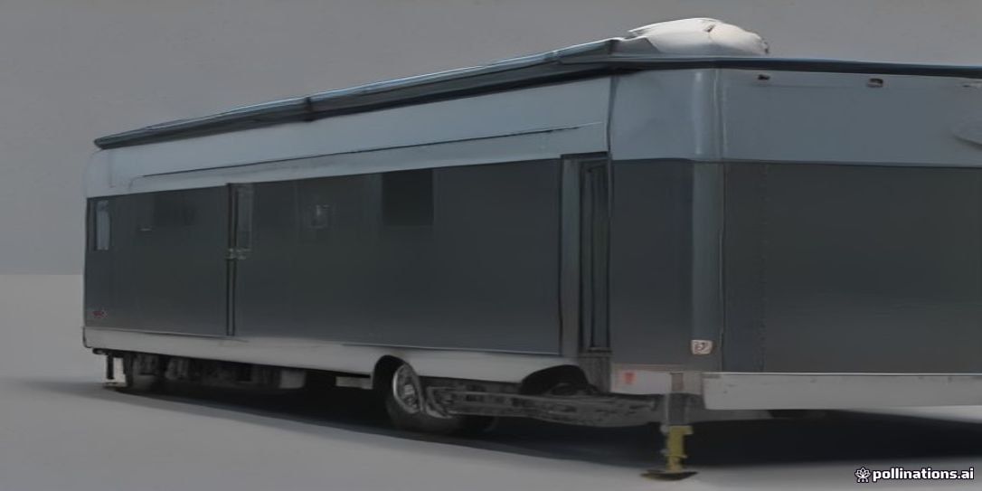
This guide presents a comprehensive engineering case study on the mechanical, dynamic, and braking safety systems between a caravan and its tow vehicle. It integrates critical aspects of towing limits, weight budgeting, dynamic stability, electric braking, and active sway control to ensure safe and efficient towing.
1. Towing Limits and Weight Budgeting
Adhering to towing limits is foundational for safe caravan operation, involving analysis of tow vehicle and caravan mass ratings for compatibility.
Key Terminology
- Gross Combined Mass (GCM): Maximum permissible total mass of the tow vehicle and coupled, loaded caravan.
- Gross Vehicle Mass (GVM): Maximum permissible total mass of the tow vehicle, including tare, occupants, fuel, and cargo.
- Aggregate Trailer Mass (ATM): Total mass of the uncoupled caravan, with maximum load, resting on its wheels and jockey wheel. Includes tare weight and payload.
- Tare Weight: Mass of the vehicle or caravan unladen, with standard equipment, fluids, and full fuel (for vehicles), but without occupants or cargo.
- Maximum Braked Towing Capacity: Maximum mass a tow vehicle is legally permitted to tow with an effective trailer braking system.
- Maximum Towball Download (TBD): Maximum vertical force the caravan’s coupling can exert on the tow vehicle’s towbar.
Deriving Vehicle and Caravan Matching Margins
Consider the following scenario:
Tow Vehicle Specifications:
- Tare Weight: 2200 kg
- GVM Limit: 3000 kg
- GCM Limit: 6000 kg
- Maximum Braked Towing Capacity: 3500 kg
- Maximum Towball Download: 350 kg
Caravan Specifications:
- Tare Weight: 2200 kg
- ATM Rating: 2800 kg
- Payload Capacity: 600 kg
- Axle Group Rating: 3000 kg
- Design Nose Weight: 250 kg (8.93% of 2800 kg ATM)
Calculations for Safe Matching:
- Caravan’s Maximum Operating Mass: The caravan’s ATM is 2800 kg.
- Tow Vehicle’s Towing Capacity Check: The tow vehicle’s maximum braked towing capacity is 3500 kg. Since the caravan’s ATM (2800 kg) is less than 3500 kg, the tow vehicle can tow the caravan.
- Margin: 3500 kg - 2800 kg = 700 kg.
- Gross Combined Mass (GCM) Check:
- Assumption: Tow vehicle is at its GVM limit and the caravan is at its ATM limit.
- Tow Vehicle at GVM: 3000 kg
- Caravan at ATM: 2800 kg
- Combined Mass: 3000 kg (tow vehicle GVM) + 2800 kg (caravan ATM) = 5800 kg
- GCM Limit Check: The calculated combined mass (5800 kg) is less than the GCM Limit (6000 kg).
- Margin: 6000 kg - 5800 kg = 200 kg.
- Towball Download (TBD) Check: The caravan’s design nose weight is 250 kg. The tow vehicle’s maximum towball download is 350 kg.
- Margin: 350 kg - 250 kg = 100 kg. The design nose weight is within the limit.
- Actual towball download must be verified once the caravan is loaded. For details on optimizing payload, refer to the guide on Caravan Payload, Axle Load, & Nose Weight Calculator: Optimize Stability & Safety.
Summary of Margins:
| Limit Type | Tow Vehicle Limit (kg) | Caravan Max Mass (kg) | Combined Mass (kg) | Calculated Margin (kg) | Status |
|---|---|---|---|---|---|
| Towing Capacity | 3500 | 2800 (ATM) | N/A | 700 | Compliant |
| Gross Combined Mass | 6000 | N/A | 5800 | 200 | Compliant |
| Towball Download | 350 | 250 (Design) | N/A | 100 | Compliant |
These calculations demonstrate that the proposed combination falls within limits, offering adequate safety margins. However, these are theoretical maximums. Real-world loading, passenger numbers, and accessory additions will affect these values. Post-assembly verification at authorized weighbridges is essential.
2. Polar Moment of Inertia and Yaw Dynamics
Beyond static weight limits, dynamic stability is paramount. Weight distribution, caravan dimensions, and resulting moments of inertia influence behavior at speed or during maneuvers.
Weight Distribution and Polar Moment of Inertia
The placement of heavy items within the caravan profoundly impacts its polar moment of inertia, which measures resistance to angular acceleration (rotation around its vertical axis, or yaw).
- Principle: Heavy loads should be positioned as close as possible to the axle line.
- Impact: Placing heavy items at the extreme front or rear increases polar moment of inertia. This makes it harder to recover from sway once it begins, potentially leading to slow, oscillating sway that escalates into uncontrollable snaking.
- Optimal Strategy: Concentrate mass near the center of gravity, ideally over or slightly forward of the axle(s). This minimizes polar moment of inertia, allowing quicker, more predictable response to corrective actions.
Nose Weight Ratio and High-Speed Stability
Nose weight is the downward force exerted by the caravan’s coupling on the tow vehicle’s towbar. It is critical for preventing sway.
- Importance: Sufficient nose weight ensures proper coupling, preventing the caravan from lifting the tow vehicle’s rear and reducing traction. Too little nose weight can lead to severe sway.
- Optimal Ratio: The generally accepted guideline is 7-10% of the caravan’s ATM. Our caravan’s design nose weight of 250 kg, with an ATM of 2800 kg, yields a nose weight ratio of (250 kg / 2800 kg) * 100% = 8.93%. This falls within the recommended range, contributing significantly to high-speed stability.
- Excessive Nose Weight: While insufficient nose weight is dangerous, excessive nose weight can overload the tow vehicle’s rear axle, reduce steering effectiveness, and compromise braking. Weight distribution hitches can help mitigate excessive nose weight by distributing some load to the tow vehicle’s front axle and the caravan’s axles. For detailed guidance, see Complete Caravan Payload, Axle Load, and Nose Weight Management System Design for Optimal Stability & Safety.
Yaw Dynamics
The physical length of the caravan, particularly the distance from the coupling point to the caravan’s axle(s), plays a role in yaw dynamics. A longer distance can increase the leverage for sway. The placement of the axle group relative to the caravan’s overall length is critical for dynamic stability.
3. Electric Brake Systems and Proportional Brake Controller Calibration
Effective braking is non-negotiable for towing safety. Electric brake systems on caravans provide independent braking capability, which must be seamlessly integrated and calibrated with the tow vehicle’s braking system.
12V Dual-Axle Drum Brake Wiring
Our caravan is equipped with 12V dual-axle electric drum brakes. This configuration requires robust wiring for reliable braking force to all four wheels.
-
Wiring Diagram (Simplified):
- Dedicated 12V power from the tow vehicle (via an Anderson plug or main tow harness) runs to the electric brake controller.
- The brake controller receives a signal from the tow vehicle’s brake light circuit.
- The controller sends a modulated voltage signal to the caravan’s electric brakes, typically through the 7-pin or 12-pin trailer plug.
- Each electric drum brake contains an electromagnet that, when energized, activates the shoes.
- For dual-axle, the controller output is split to supply both axles, usually wired in parallel.
-
Emergency Breakaway Circuit: A crucial safety feature. If the caravan detaches, a breakaway switch (activated by a lanyard) applies maximum voltage from an onboard 12V battery (e.g., a 12V 5Ah SLA battery) to all caravan brakes, bringing it to a rapid stop. This circuit must be independent of the tow vehicle’s power and braking systems.
Accelerometer-Based Proportional Brake Controller Calibration
A proportional electric brake controller uses an internal accelerometer to sense the tow vehicle’s deceleration, applying proportional braking force to the caravan. This results in smoother, more controlled stops than time-delay controllers.
- Controller Model: Proportional Electric Brake Controller.
- Initial Gain Setting: 5.5.
Calibration Procedure (Practical Example):
- Preparation:
- Ensure the caravan is fully loaded to its typical travel weight (e.g., 2800 kg ATM).
- Find a safe, level, paved area with no traffic.
- Connect the caravan to the tow vehicle.
- Ensure the brake controller is securely mounted in the tow vehicle, level and facing the direction of travel, for accurate accelerometer readings.
- Initial Test - Low Speed:
- Drive at 25 km/h.
- Activate the manual override lever on the brake controller without using the tow vehicle’s brakes.
- Observation: Caravan brakes should engage gently. The initial gain setting of 5.5 should provide noticeable braking.
- Adjustment (if needed): Reduce gain if brakes lock up or feel aggressive; increase if braking is minimal.
- Refined Test - Moderate Speed:
- Drive at 40-50 km/h.
- Apply the tow vehicle’s brakes moderately, as in normal driving.
- Observation: Braking should feel smooth and synchronized. No push from the caravan (too little gain) or strong tug/jerking (too much gain). The caravan should decelerate at a similar rate.
- Adjustment: Incrementally adjust gain (e.g., by 0.5) until braking feels balanced. The tow vehicle and caravan should slow down as a single unit.
- Our initial setting of 5.5 is a good starting point. Fine-tuning around this value will achieve optimal performance.
- Final Verification: Perform several stops at various speeds and braking intensities. The system should provide consistent, controlled braking.
Safety Boundary: All brake wiring must conform to local road standards (e.g., ECE R13 / VSB1). Incorrect wiring can lead to brake failure.
4. Active Sway Control (AL-KO ATC / Dexter DSC) Integration
Active Sway Control (ASC) systems provide an automated layer of protection against dangerous sway events by monitoring and intervening proactively.
System Overview (AL-KO ATC / Dexter DSC)
Our scenario specifies the integration of an AL-KO ATC (Automatic Trailer Control) system. Dexter DSC (Dexter Sway Control) operates on similar principles.
- Function: These systems continuously monitor the caravan’s lateral movement. If sway is detected beyond a threshold, the system automatically and gently applies the caravan’s electric brakes to correct movement and stabilize the trailer. This happens without driver intervention.
- Mechanism:
- Sensors: An internal sensor (gyroscope or accelerometer) detects the caravan’s yaw rate and lateral acceleration.
- Processing: A control unit analyzes these sensor inputs in real-time.
- Intervention: If inputs indicate dangerous sway, the control unit signals the caravan’s electric brakes.
- Braking: Brakes are applied briefly and lightly, creating drag that pulls the caravan back into line. This braking is subtle and designed to stabilize, not stop the caravan.
Integration Requirements
- 12V/15A Uninterrupted Power Supply: The AL-KO ATC system requires a continuous, fused 12V power supply.
- Source: Typically from the tow vehicle’s battery, routed via an Anderson plug or dedicated heavy-gauge wire.
- Fuse: A 15A fuse is critical.
- Function: Ensures the system is always active and monitoring.
- Sensor Alignment Tolerances:
- Mounting: The ATC unit must be mounted securely within the caravan, typically on the chassis or floor, to accurately reflect movement.
- Orientation: The unit must be mounted level and correctly oriented with the direction of travel (indicated by arrows). Misalignment leads to inaccurate sensor readings.
- Calibration: Some systems require initial calibration by an authorized technician to ‘learn’ the caravan’s operating parameters.
- Automatic Emergency Braking Logic:
- The AL-KO ATC’s core logic is to intervene without destabilizing the tow vehicle. The braking force is minimal and targets only the caravan.
- It is distinct from the tow vehicle’s braking system; it does not activate the tow vehicle’s brakes.
- The system’s goal is to dampen oscillations, not to bring the combination to a stop, ensuring the driver maintains full control.
Safety Boundary: Installation of active sway control systems should ideally be performed by qualified technicians to ensure correct mounting, wiring, and calibration, adhering to manufacturer guidelines and local regulations.
Component Summary
| Component | Function |
|---|---|
| Tow Vehicle | Provides motive power, primary braking, and electrical supply; defines GVM, GCM, and towing capacity limits. |
| Caravan | Trailer unit; defines ATM, payload, nose weight, and dynamic characteristics. |
| Electric Drum Brakes (12V Dual-Axle) | Provides independent braking for the caravan, essential for safety and stability. |
| Proportional Electric Brake Controller | Senses tow vehicle deceleration and proportionally applies caravan brakes for smooth, synchronized stopping. |
| Breakaway Switch & Battery (12V 5Ah SLA) | Activates maximum caravan braking automatically if the caravan detaches from the tow vehicle. |
| AL-KO ATC / Dexter DSC (Active Sway Control) | Continuously monitors caravan sway and automatically applies gentle braking to stabilize the caravan before sway becomes dangerous. |
| Weight Distribution Hitch (Optional but Recommended) | Distributes towball load more evenly across tow vehicle axles, improving stability and handling. |
Safety Warning
All electrical wiring for braking systems and tow hitch load limits must comply with local road standards (e.g., ECE R13 / VSB1). The values provided in this guide are for engineering scenario modeling. Final verification by authorized weighbridges and expert technicians is mandatory after installation and loading. Always consult your vehicle and caravan owner’s manuals for specific limits and recommendations.
Sources and Assumptions
- Towing Limits and Masses: Canonical Numeric Data Contract values are assumed to be manufacturer specifications.
- Braking Systems: The specified 12V Dual-Axle Electric Drum Brakes, Proportional Electric Brake Controller, and initial gain setting of 5.5 are illustrative model specifications. Actual settings may vary based on specific controller models and caravan characteristics.
- Active Sway Control: The AL-KO ATC system (12V Supply, 15A Fuse) is an illustrative model. Specific installation and operational guidelines should be sourced from the AL-KO or Dexter manufacturer manuals.
- Local Regulations: ECE R13 (Economic Commission for Europe Regulation 13) and VSB1 (Vehicle Standards Bulletin 1, Australia) are cited as examples of national/international road standards for braking and vehicle construction. Users should verify applicable standards in their specific jurisdiction.